
LX Data Sheet
with hQ-dB-CAD verification as a planning basis and proof of system performance
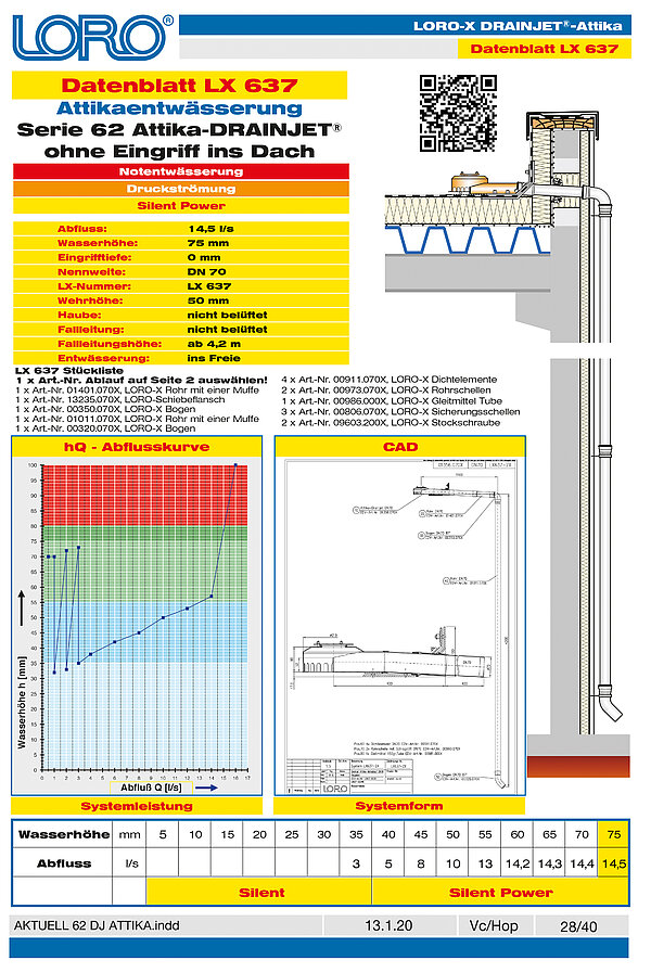
Performance through form: Each LX data sheet contains a clear presentation of the defined form characteristics and the measured performance characteristics of a complete system.
DIN 1986-100 5.7.3.1: "The manufacturer must specify the discharge capacity of the roof drain as a function of the pressure height in the form of a table or diagram."
LORO conducts all measurements on its own test facilities with CAD-accurate description of the measured system and documents the measurement points as a discharge curve and table in each LX data sheet, enabling clear and traceable specifications of the measurement results at any time.
hQ-dB-CAD stands for the measured proof of:
h = Water height on the roof in millimetres
Q = Discharge from the roof in litres per second
dB = Silent, Silent-Power, Power class
CAD = System form as drawing and parts list
Page 1: LX Number and Description
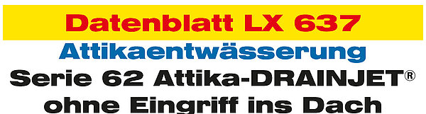
The LX number uniquely identifies the LORO-X complete system and makes it easy to find. In the online product database, all available LX data sheets are stored and are available either via the LX number or via the article number of the drain.
The description contains a brief description of the system with the name of the series and model.
LORO-X Feature Bar
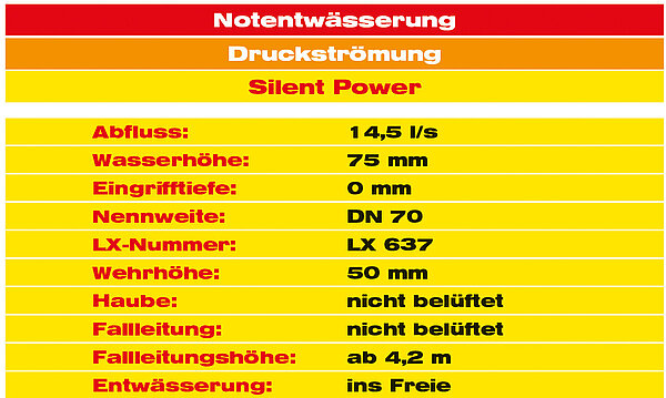
In the feature bar you will find the essential characteristics of the system shown in the LX data sheet.
In this example, you can see that it is a DN70 emergency drainage system with Silent-Power siphonic flow, with a nominal discharge of 14.5l/s at a nominal water height of 75mm.
For main-emergency-combination systems, this information is displayed in two columns, one for the flow path of the main and emergency drainage. Alternatively, there may be several separate LX data sheets for combined systems.
The nominal discharge and nominal water height are also highlighted in yellow in the table of the discharge curve.
LORO-X Discharge Curve
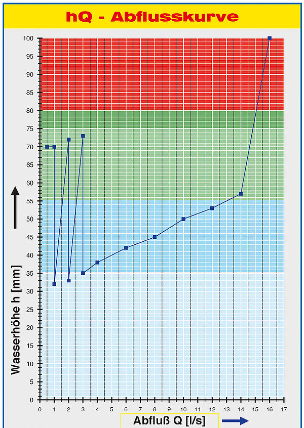
The core element of each LX data sheet is the measured discharge curve (system performance) in conjunction with the CAD drawing (system form).
The measurement of the performance characteristics water height (Y-axis) and discharge (X-axis) is carried out by LORO on purpose-built test facilities with powerful water circuits, on which the various complete systems are installed and measured with CAD-accurate system form.
The background colour of the diagram symbolises different areas defined by certain threshold values:
1. Area (light blue): With gravity flow, the nominal discharge is read at a nominal water height of 35mm.
2. Area (dark blue): With siphonic flow, the nominal discharge is read at a nominal water height of 55mm.
3. Area (light green): Sound values in this area are considered a Silent solution (<75dB), which corresponds to the babbling of a brook. Values in this area are below the waking threshold for humans. The nominal discharge for emergency drainage systems is also read at this water height (75mm).
4. Area (dark green): The Silent-Power area is situated between the quiet Silent gravity flow and the strong Power siphonic flow. It is a transition area where a Silent gravity flow system is overloaded and suction effects can already occur.
5. Area (red): Power siphonic flow with high discharge values, where sound levels at a distance of 0.5m above the drain may exceed 80dB.
CAD Drawing and Application Graphic
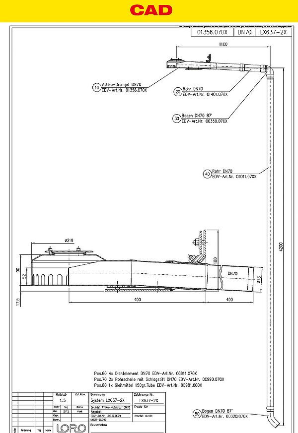
The CAD drawing shows the test system (system form) for the measurement values of the discharge curve (system performance).
In this example, the system is deflected with an unvented elbow so that the suction effect of the downpipe is transported to the drain. The downpipe is assumed in the measurements with a height of 4.2m including rainwater standpipe (main drainage) or outlet to the open (emergency drainage).
The application graphic of the complete system shows a typical installation situation for the system.
Page 2: Flange Types and Dimensions
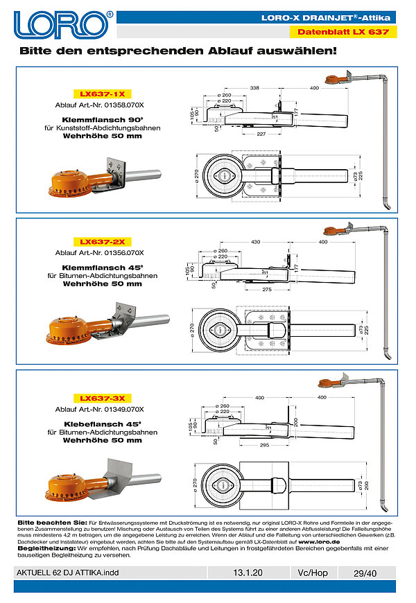
On the second page of the LX data sheet you will find various flange types for connection that lead to the same discharge values.
The available flange type is appended to the LX number (e.g. LX637) using the following system to obtain a unique parts list in the product database. In this example, e.g. LX637-1X, LX637-2X,...
-1X = Parapet clamping flange 90 degrees
-2X = Parapet clamping flange 45 degrees
-3X = Parapet adhesive flange 45 degrees
-4X = Parapet clamping flange without upstand
-21X = Parapet adhesive flange 90 degrees
-5X = Roof single-piece without thermal insulation
-6X = Roof two-piece without thermal insulation
-7X = Roof single-piece with thermal insulation
-8X = Roof two-piece with thermal insulation
-9X = Roof single-piece with thermal insulation with heating
-10X = Roof two-piece with thermal insulation with heating
-11X = Roof with factory-fitted connection sleeve
-20X = Adhesive flange folded spout
-12X = Balcony single-piece without thermal insulation
-13X = Balcony two-piece without thermal insulation
-14X = Balcony single-piece with thermal insulation
-15X = Balcony two-piece with thermal insulation
-30X = Measured articles, combinable with others acc. to page 2 (e.g. DN100/50/50, flat dome)
To plan the necessary openings in thermal insulation and parapet upstand for the drain, you will also find the required dimensions of the drain and a selection of essential system parts on this page.
Characteristics for Specifications
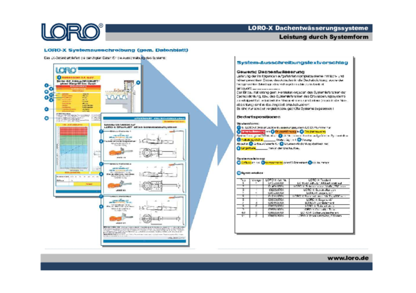
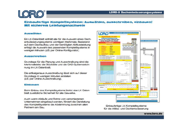
Feature Bar
The LORO-X feature bar compiles essential characteristics of a roof drainage system with its specific attributes so that these can be adopted into the specification. Based on the characteristic attributes, different systems can be quickly compared.
Parts List
The parts list contains all system parts of the measured system with article number and quantity, ready for installation. Often, for project-specific specifications, only the number of straight pipes for the downpipe needs to be adjusted to the building.
Discharge Curve
The discharge in litres per second (l/s) and the water height on the roof (mm) are clearly shown in the discharge curve and in table form. Each roof drainage system has a specific discharge curve. The "flatter" the curve, the "faster" the drainage.
CAD System Drawing
The CAD system drawing shows the measured standard system with all important functional parts. The CAD drawing is available under the corresponding LX number in the product database as a 2D-PDF, 2D-DWG and 3D-DWG document for download.
2D Application Graphic
The 2D application graphic illustrates the installation of the roof drainage system in the roof structure.