
LORO-X DUOSTREAM Cascade Drainage
7 Steps to Design the LORO-X DUOSTREAM Cascade Drainage
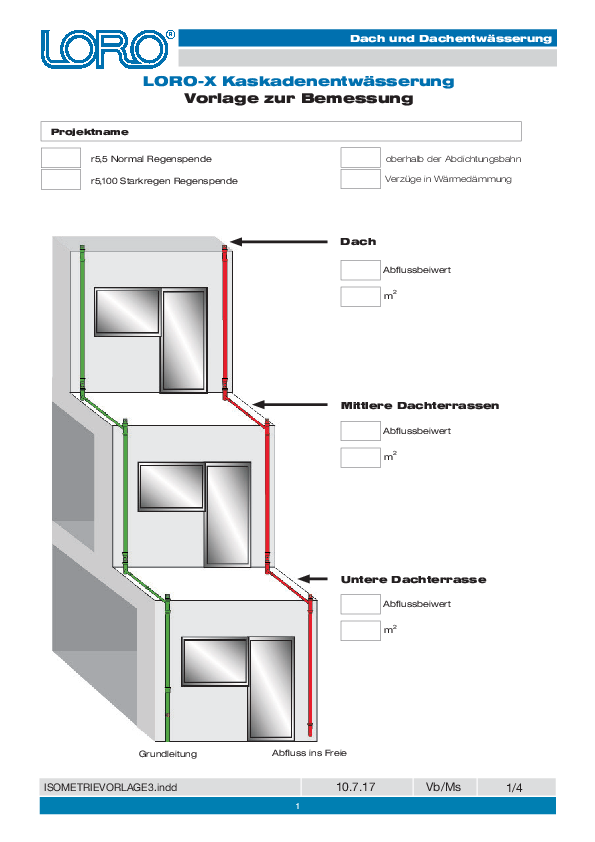
When designing the LORO-X DUOSTREAM cascade drainage with multi-storey drains, it must be taken into account that the discharge from each storey accumulates in the continuous collecting pipe (stream) running from top to bottom. As the discharge increases towards the bottom, the "lower" storey becomes decisive as it limits the overall performance of the stream.
In the following steps, we would like to describe the procedure for designing a system with multi-storey drains and pressurised gravity flow using an example.
Design and Calculation Principles
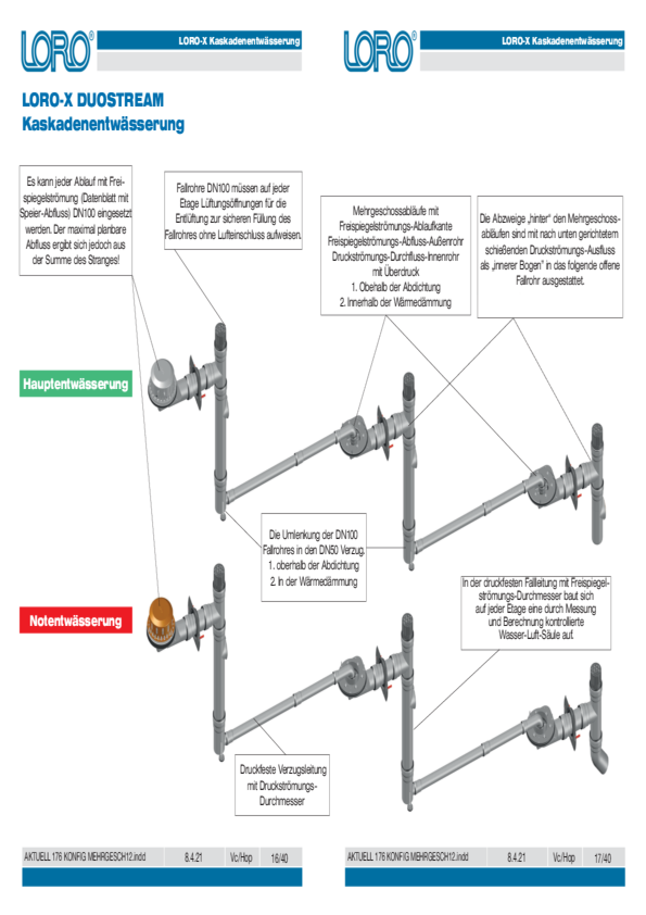
First, the height of the downpipe per storey (limit min. 2.5 m!) and the length of the horizontal offset per storey must be checked (limit max. 8 m!). If one of the mentioned limits cannot be met, please contact LORO, as the streams will then be hydraulically calculated by us.
The calculation of the discharge in l/s can be carried out with the online calculation just as for conventional roof drainage for each storey (Steps 1-4).
Then the pipe routing of Stream 1 (main drainage) and Stream 2 (emergency drainage) is described. The discharge QMain and QEmergency per storey is accumulated (Step 5). The limit of 4 l/s or 8 l/s per stream must be observed for the total (Step 6).
Then the parts list for Stream 1 and Stream 2 is determined (Step 7). For this purpose, one of the templates prepared by LORO for standard parts lists can be used (PDF linked next to this text). This template only needs to be adapted to the specific project, depending on the height of the downpipes and lengths of the horizontal offsets.
For a quick overview, we have summarised important design principles for the DUOSTREAM cascade drainage with pressurised gravity flow in the adjacent PDF!
Example
Heights and Lengths

In order to build up sufficient overpressure in the DN100 downpipe, the height of the downpipe used for the measurement from each storey to the storey below should be at least 2.5 m. Measure the height of the downpipes from the respective upper storey to the storey below from the bottom edge of the collecting box to the centre of the horizontal offset. H1 is the height of the downpipe from the roof to the middle roof terrace and H2 from the middle roof terrace to the lower roof terrace. In our example, we assume the same storey height.
H1 = 2.75 m
H2 = 2.75 m
In order not to build up too much pressure loss in the DN 50 offset, the length of the horizontal offset (L) used for the measurement should not exceed 8 m. In our example, we assume the same depth of the roof terraces. L1 is the length of the horizontal offset across the middle roof terrace and L2 across the lower roof terrace.
L1 = 4.0 m
L2 = 4.0 m
If H is less than 2.5 m or L is longer than 8 m, the LORO Service Team must be contacted for hydraulic calculation!
Step 1: Local Rainfall Intensity
First, the rainfall intensity for main drainage (normal rainfall intensity (r(5,5))) and emergency drainage (heavy rainfall (r(5,100))) is determined from KOSTRA based on the postcode of the building project. For our example, we assume a rainfall intensity of 300 / 600. We are happy to provide the exact rainfall intensity based on the postcode of your building project.
Main drainage: r(5,5) = 300 l/s/ha
Emergency drainage: r(5,100) = 600 l/s/ha
Step 2: Size of the Drainage Areas
The size of the effective drainage areas (A) of the roof and roof terraces is determined by the building. In our example, we have a roof area of 50 m2, as well as two equally sized roof terraces with 30 m2 each, arranged in a cascade.
A Roof = 50 m2
A middle roof terrace = 30 m2
A lower roof terrace = 30 m2
Step 3: Runoff Coefficient of the Roof Structures
The runoff coefficient (C) for the roof and the roof terraces is determined based on the structure of the drainage area. In our example, we assume a smooth surface as a waterproofing membrane without gravel or vegetation for the roof and both roof terraces. The runoff to the drains is thus not impeded, so a runoff coefficient of 1.0 is selected.
C Roof = 1.0
C middle roof terrace = 1.0
C lower roof terrace = 1.0
Step 4: Discharge per Multi-Storey Drain
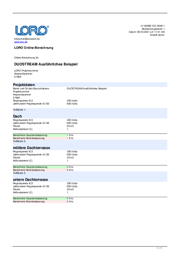
The required discharge for main drainage (QrMain) and emergency drainage (QrEmergency) for the roof and the roof terraces can be calculated with the online calculation. The values for rainfall intensity, areas and runoff coefficients from Steps 1-3 are required for the calculation. The discharge calculated in this step must be able to flow from the drainage area into the multi-storey drain with gravity flow. According to the LX data sheet, it must be ensured that the available nominal discharge of the multi-storey drain is sufficient.
Stream 1 Main Drainage
QrMain Roof = 1.5 l/s
QrMain middle roof terrace = 0.9 l/s
QrMain lower roof terrace = 0.9 l/s
Stream 2 Emergency Drainage
QrEmergency Roof = 1.5 l/s
QrEmergency middle roof terrace = 0.9 l/s
QrEmergency lower roof terrace = 0.9 l/s
Step 5: Discharge per Stream (Sum of all Drains)
While in Step 4 the inflow from each individual area through the multi-storey drain into the stream was calculated, in Step 5 the sum of the inflows in the direction of flow (from top to bottom) is calculated. This gives the "utilisation" of the pipe system on each storey, which increases with the inflow from each multi-storey drain.
QrSumStreamMain = 1.5 + 0.9 + 0.9 = 3.3 l/s
QrSumStreamEmergency = 1.5 + 0.9 + 0.9 = 3.3 l/s
Note: The available nominal discharge of the drains on the roof and the multi-storey drains on the roof terraces from the respective LX data sheet must not be considered per storey alone, but must take into account the discharge of the entire stream across all storeys (totals from Step 5). Even if a multi-storey drain alone can already handle up to 4 l/s, the permissible system capacity of a maximum of 4 l/s would already be exhausted with one drain or on one storey. The maximum size of the roof and roof terraces is therefore not limited by the performance of the individual multi-storey drains, but by the accumulated performance of the entire stream!
Step 6: Offset with Single Pipe or Double Pipe
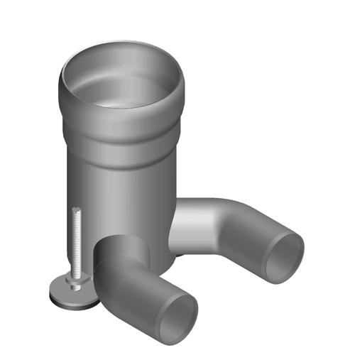
Since the flow through the horizontal offset is limited, it must be checked whether the totals from Step 5 can be pushed through the respective offset. The individual inflows from the multi-storey drains above can vary depending on the size of the areas, as long as the total in the pipe system is not exceeded. If the total results in a higher discharge than 8 l/s, an additional stream must be provided from this storey.
Sum of one stream up to 4 l/s: Offset with one pipe DN 50
Sum of one stream from 4-8 l/s: Offset with double pipe DN 50 for high performance
In our example, we are below 4 l/s per stream with a total of 3.3 l/s, so we can use a single pipe DN 50 for all offsets.
Step 7: Parts List for Both Streams
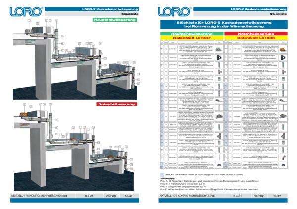
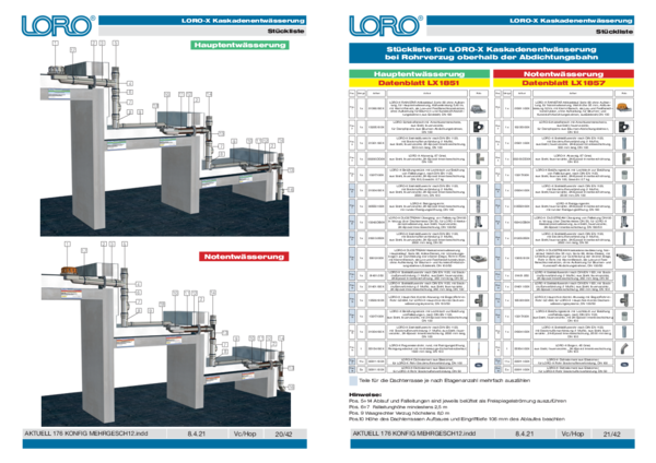
For easy creation of the parts list, we have prepared standard parts lists for the main and emergency drainage either with the offset within the thermal insulation or above the waterproofing membrane, which you can download directly as a PDF. In the online specification, further project-specific adjustments can be made before ordering, e.g. the pipe lengths and pipe clamps for downpipes and offsets. For the horizontal offsets in DN50, pipes with a long sleeve are particularly suitable for installation between 2 fixed points.
The complete offer consists of a printout of the online calculation for all storeys, the online specification with parts list for the main and emergency drainage streams, and the LX data sheets for the drains used as performance verification with measured flow curves.