
LORO-X Retention Roof Drainage (Design)
Example: In 17 steps to strong retention with strong emergency drainage

For the offered VARIOFIT retention units, the following planning specifications are required during the ordering process:
- Retention discharge (QRet): Desired discharge of the retention unit in l/s (Step 3).
- Retention water level (hRet): Planned water accumulation height on the roof (Step 6).
- Retention pipe height (hRetpipe): Recommendation: min. 40 mm above the water level of the emergency drainage (Step 7).
- Permanent ponding (HSlotBottom): If permanent ponding is required on the waterproofing surface for irrigation purposes (Step 10).
- Weir height emergency drainage (hWeir): Recommendation: top of retention box and depending on the structural capacity (Step 14).
In the following 17 steps, an example describes how these planning specifications are determined and how the design of the main drainage with retention and the emergency drainage with height-variable weir is carried out.
For further questions or assistance with the design, our technical team looks forward to your call at Tel. +49 5382-71-470!
Roof Area and Rainfall Intensity
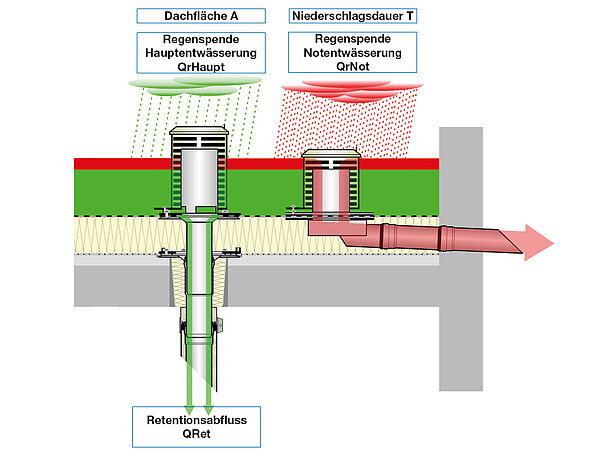
Step 1: Determine the size of the (partial) roof area in square metres for the retention roof drainage.
Example: A = 150 m2
Step 2: Determine the inflow in l/s based on the rainfall intensity for the main drainage and emergency drainage using the online calculation.
Example: QrMain = 3 l/s
Example: QrEmergency = 3 l/s
Step 3: Define the required retention discharge for the main drainage (QRet) (e.g. specification by the municipality).
Example: QRet = 1 l/s
Step 4: Determine the assumed rainfall duration (e.g. specification by the planning).
Example: T = 1500 sec (25 min)
Water Level
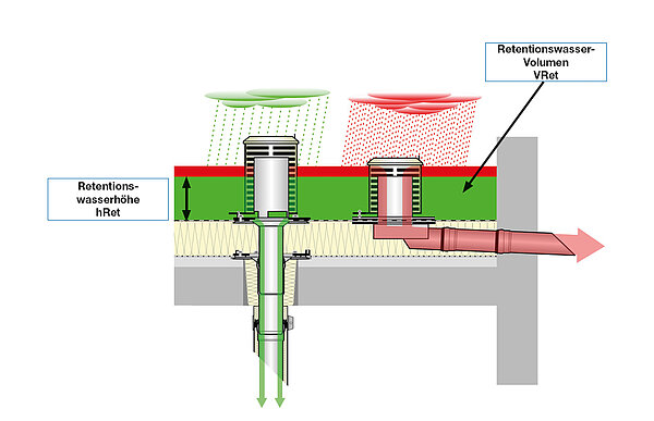
Step 5: Calculate the retention water level (hRet).
First, the retention water volume (VRet) is calculated, which falls on the area (A) as rainfall intensity for main and emergency drainage (QrMain + QrEmergency) during the rainfall duration (T), and the water volume that drains from the roof through the retention discharge (QRet) during the rainfall duration (T).
Example: VRet = (QrMain + QrEmergency - QRet) * T = 7.5 m3
This retention water volume (VRet) is then converted to the area (A), resulting in the planned retention water level (hRet).
Example: hRet = VRet / A = 0.05 m (= 50 mm)
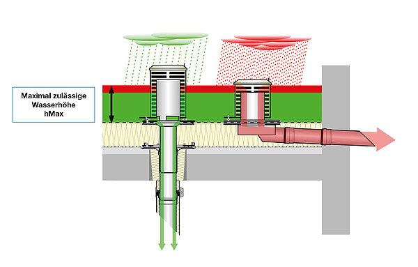
Step 6: Define the maximum permissible water level (hMax).
The maximum permissible water level (hMax) is measured from the top of the loose flange and is determined by the structural capacity of the roof (e.g. maximum roof load) or by the roof construction (e.g. spacer height). It represents the water level that must not be exceeded even during emergency drainage operation.
Example: hMax = 85 mm
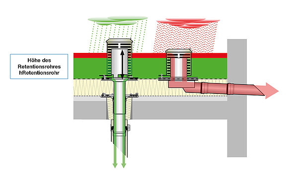
Step 7: Determine the height of the retention pipe (hRetentionPipe).
The height of the retention pipe (hRetentionPipe) depends particularly on the maximum permissible water level (hMax). It should be determined to be at least equal to or higher than hMax and fulfil the following tasks:
A) Ensure the ventilation of the gravity flow.
B) Prevent overflow into the retention pipe, as the water would otherwise flow unthrottled from above into the retention pipe and the retention function would no longer be provided.
If the height of the retention pipe cannot be determined above hMax for structural reasons, the retention pipe can be sealed at the top. In this case, the manufacturer must verify whether siphoning can be excluded even without ventilation.
Example: hRetentionPipe = hMax = 85 mm
Retention Pipe
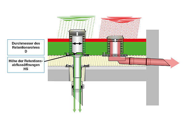
Step 8: Determine the diameter of the retention pipe (D).
The circumference of the retention pipe is calculated from the diameter of the retention pipe (D), which is used to verify whether the calculated slot length fits on the circumference. The diameter of the retention pipe (D) results from the choice of retention drain and can be read from the drawing of the retention drain (cf. Step 13).
D = 125 mm
Step 9: Specification of the height of the retention discharge openings (HS).
The height of the retention discharge openings (HS) is specified as standard at 20 mm and is only changed if the circumference of the retention pipe is too small for the calculated length of the retention discharge openings.
HS = 20 mm
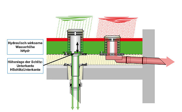
Step 10: Determine the height position of the bottom edge of the retention discharge openings from the drainage level (HSlotBottom).
If the height position of the bottom edge of the retention discharge openings from the drainage level (HSlotBottom) is chosen above 0 mm, permanent ponding occurs on the roof at this water height, as no water can drain below the retention discharge openings.
Example: HSlotBottom = 0 mm
Step 11: Calculation of the hydraulically effective water level.
The hydraulically effective water level above the slot bottom edge (hHydr) is calculated from the retention water level (hRet) and the height position of the bottom edge of the retention discharge openings from the drainage level (hSlotBottom).
Example: hHydr = hRet - hSlotBottom = 50 mm.
Retention Discharge Openings
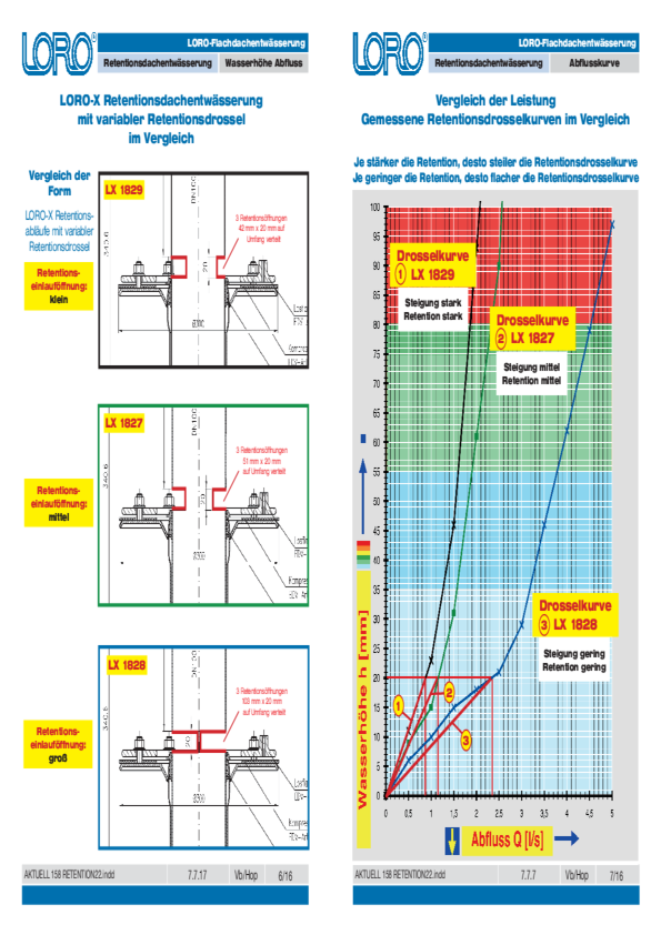
Step 12: Calculate the size of the retention discharge openings.
The size of the retention discharge openings is calculated using the formula developed by LORO and confirmed by measurement.
With retention, strong throttling with a low discharge into the ground pipe leads to particularly small retention discharge openings. In practice, it has been shown that small retention discharge openings promote contamination and may require additional measures against blockage. During planning, for example, a strong emergency drainage, shorter maintenance intervals and upstream sieve baskets or inspection chambers with small slot size should be considered. It must therefore be verified and approved on a case-by-case basis whether the calculated size of the retention openings is practically applicable.
Example: Width (B) of all retention discharge openings in total: 83.46 mm.
Example: Width per retention discharge opening (LS): 83.46 / 3 = 27.82 mm.
These calculated values serve as specifications for the production of the LORO-X VARIOFIT retention units.
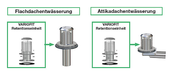
Step 13. Select retention units
The selection of the appropriate LORO-X VARIOFIT retention units is made to match the base body of the desired series.
- DN50, DN70 and DN100: VARIOFIT retention unit 14530.000X (D) = 125 mm
- DRAINLET Series 84:
- DN70 VARIOFIT retention unit 14510.070X (D) = 125 mm
- DN100 VARIOFIT retention unit 14510.100X (D) = 150 mm
- DN125 VARIOFIT retention unit 14510.125X (D) = 150 mm
Emergency Drainage
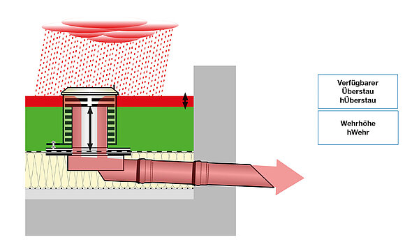
Step 14: Define the weir height (hWeir) of the emergency drainage.
The weir height (hWeir) of the emergency drainage is usually set equal to the retention water level (hRet), so that emergency drainage only occurs when the retention water level is exceeded. The retention water level is exceeded when A. it rains longer than the planned rainfall duration or B. it rains more intensely than the planned rainfall intensity for the main drainage.
Since the weir height depends on the retention water level and can vary with each drainage system, an emergency drainage with height-variable weir is recommended.
Example: hWeir = hRet = 50 mm
Step 15: Calculation of the surcharge for the emergency drainage (hSurcharge).
The available surcharge for the emergency drainage (hSurcharge) is the surcharge available above the weir for the operation of the emergency drainage. The available surcharge results from the difference between the maximum permissible water level (hMax) and the weir height (hWeir).
Example: hSurcharge = hMax - hWeir = 35 mm
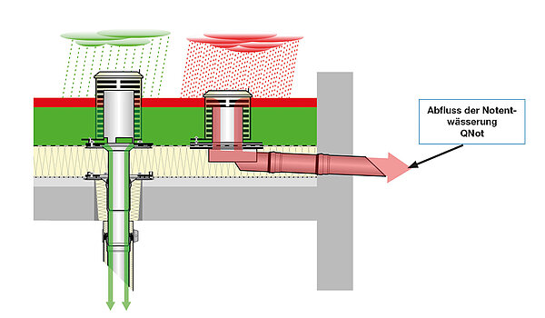
Step 16: Calculate the required discharge for the emergency drainage.
The required discharge for the emergency drainage (QEmergency) is calculated from the difference between the total rainfall intensity (QrMain + QrEmergency) minus the retention discharge for the main drainage (QRet).
Often the safety assumption is also made that the discharge for the emergency drainage (QEmergency) must equal the total rainfall intensity (QrMain + QrEmergency) without deducting the retention discharge, assuming that the retention discharge can be equal to 0.
Example: QEmergency = (QrMain + QrEmergency) - QRet = 5 l/s
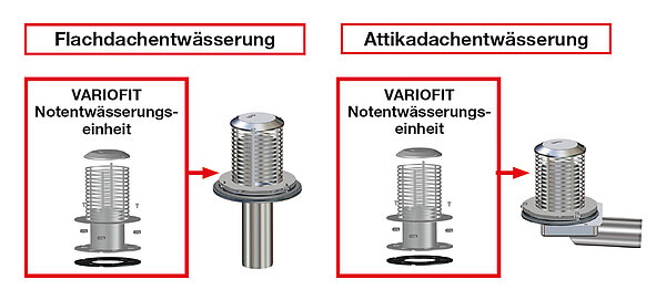
Step 17: Select the LORO-X VARIOFIT flow guide with height-variable weir.
The emergency drainage with height-variable weir is based on the discharge capacity according to the LX data sheet at the calculated surcharge (hSurcharge) and on the basis of the base body of the desired series.
- DN50, DN70 and DN100 VARIOFIT emergency drainage unit 14730.000X (D) = 125 mm
- DRAINLET Series 84:
- DN70 VARIOFIT emergency drainage unit 14710.070X (D) = 125 mm
- DN100 VARIOFIT emergency drainage unit 14710.100X (D) = 150 mm
- DN125 VARIOFIT emergency drainage unit 14710.125X (D) = 150 mm