
Planning Steps for Flat Roof Drainage
Safe and fast planning with ready-to-install complete systems – also with siphonic flow
Planners and roofing contractors are taking on increasing responsibility in construction. Building owners particularly turn to their trusted roofing contractor for flat roof renovation. Often an appointment is arranged at short notice, during which the roof area measurements are taken directly on site. The subsequent planning of optimal drainage with gravity flow or siphonic flow is then carried out promptly by the contractor or in collaboration with the planner.
Our LORO Service Team is happy to support the planning of roof drainage with siphonic flow and gravity flow based on your CAD drawing or isometry!
This article describes important aspects of roof drainage step by step from planning to installation.
Step 1: Survey and Determine Low Points
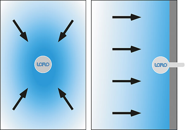
Flat roofs can be built without or with a slight slope. Usually, a slight slope results in several separate low points, or a longer low point line - for example along the parapet.
For the drainage of partial areas, each low point on the roof must be considered individually. This means that each low point or low point line must be assigned at least one main drainage to the underground pipes and additionally at least one emergency drainage to the outside.
Step 2: Choose the Drainage Path
Through the parapet or through the roof?
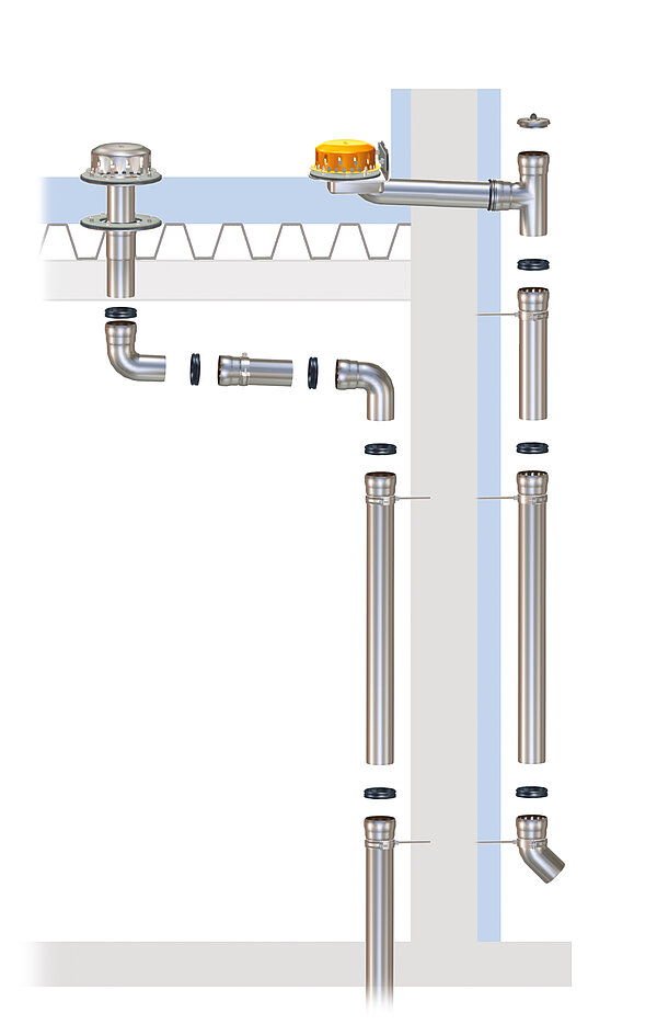
Depending on whether the low point is in the middle of the roof or at the parapet, main and emergency drainage can be realized with an external downpipe through the parapet or internally with core drilling through the roof. For new buildings and renovation projects, it can be more economical to opt for a high-performance parapet drainage without pipes inside the building.
Internal pipe systems must be backflow-proof, pressure-resistant, break-resistant, impact-resistant and insensitive to physical damage for safety against flooding in the building. External pipe systems should additionally be resistant to weather, heat, cold and UV radiation. While internal protection against condensation through composite pipes (double-walled) can be an issue, in frost-prone areas, protection against freezing condensation must be considered.
LORO-X complete systems made of hot-dip galvanized steel meet all requirements and additionally satisfy aesthetic demands.
Step 3: Calculate "Litres per Second"
with the online calculation at www.loro.de
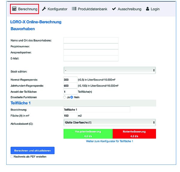
The calculation of the required flow rate in "litres per second" is performed using the calculation formula in DIN 1986-100. In this formula, the minimum required flow rate is calculated based on the size of the connected partial area in connection with the local rainfall intensity. In practice, the online calculation at www.loro.de has proven effective, providing results in just a few seconds. The additional runoff coefficient for gravel or green roofs is also considered here, as water flow to the drain is delayed by these special roof constructions.
Step 4: Select the Appropriate Drain
Depending on the roof structure and the waterproofing used
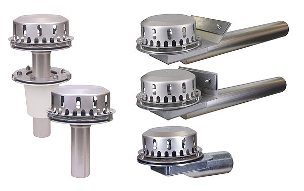
Depending on the roof structure and the waterproofing membrane used, the design of the parapet or roof drain is selected.
Vertical roof drains with practical clamping flange are suitable for almost any roof waterproofing membrane, whether made of plastic or bitumen. However, a distinction is made between so-called one-piece and two-piece roof drains. While one-piece drains only integrate the roof waterproofing membrane, two-piece drains have an additional clamping flange for the secure connection of the vapour barrier below the thermal insulation.
Parapet drains differ in terms of the upstand to the parapet, with the upstand for bitumen being standard at 45° angle and for plastic at 90° angle. A practical alternative are Attika-Distant drains without upstand, which are equally suitable for bitumen and plastic and can be installed at a variable distance of over 300mm from the parapet.
Drains with adhesive flange or connection collar are generally only suitable for bitumen. The specifications of the respective waterproofing manufacturers should always be observed.
Step 5: Determine Quantity
required discharge / delivered discharge
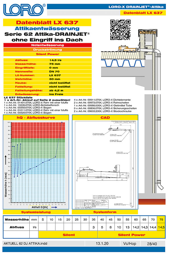
The comparison of drainage performance of roof drainage systems is made in "litres per second" at a "water height in millimetres". From the drainage curve of the LX data sheet of a roof drainage system, the drainage performance (in l/s) can be read at any water height (in mm).
Generally, a higher water height on the roof results in higher drainage performance of the drainage system. However, particularly effective roof drainage systems achieve maximum drainage performance even at minimal water height on the roof.
The number of drainage systems then depends on the calculated drainage performance (cf. Step 3) and the actual drainage performance of the roof drainage system (cf. LX data sheet). The higher the drainage performance of a parapet or roof drainage system, the fewer drains and downpipes are needed!
Number of drainage systems = required drainage / delivered drainage
Conclusion
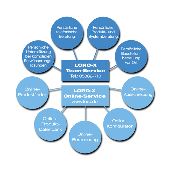
For roofing contractors, planning, optimization and installation of complete siphonic drainage systems from a single source is easily possible. LORO as a system provider offers the necessary support from planning in the office to installation on the construction site and delivers drains, pipes, fittings and fixing materials optimally coordinated from a single source.
Further system solutions as well as helpful programs for calculation, configuration and quotation preparation can be found at www.loro.de. All online functions are also compatible with mobile devices without having to download special apps. We also look forward to your call or email!